eISSN: 2093-8462 http://jesk.or.kr
Open Access, Peer-reviewed
eISSN: 2093-8462 http://jesk.or.kr
Open Access, Peer-reviewed
Jinsol Cheon
, Seongjong Park
10.5143/JESK.2023.42.1.15 Epub 2023 March 03
Abstract
Objective: The aim of this study is to evaluate if personnel on board can evacuate safely in emergency during hook-up and commissioning phase of offshore production facility.
Background: As an offshore facility is operated remotely from land, the safety of operators becomes more significant when they are exposed to various hazards such as fire, explosion, ship collision and etc. Therefore, it is important to arrange available evacuation means properly and check other related elements in advance. For these reasons, evacuation analysis for normal operation phase is performed in the design stage. However, during hook-up and commissioning phase, the number of operators on board the facility could become double compared to the normal operation phase. Therefore, evacuation analysis should be performed for this phase and evacuation means including life-saving appliances should be additionally installed to secure the safety of increased operators.
Method: Evacuation time analysis is based on defining actions and assumptions for various stages of evacuation. For time calculation, evacuation scenarios should be established first. Depending on the evacuation means, escape routes and procedures change. Then, time for each evacuation stage is accumulated to determine if time requirement could be met. The integrity of temporary refuge system is also checked if it can accommodate the increased number of personnel in emergency.
Results: Based on various rules and regulations such as IMO, ISO, ABS, and etc., the needed quantity of life-saving appliances and the integrity of the temporary refuge were checked to ensure the safety of operators prior to evacuation. Temporary refuge system can accommodate the increased number of operators. Three evacuation scenarios are established and total evacuation time of all scenarios satisfy the time requirement.
Conclusion: As the number of evacuees is a dominant factor in evacuation time calculation, evacuation during hook-up and commissioning phase when the number of operators on board dramatically increases should be separately evaluated.
Application: The results of the evacuation analysis might help to establish the evacuation scheme of offshore facilities during hook-up and commissioning phase.
Keywords
EER (Escape Evacuation and Rescue) Evacuation safety HUC (Hook-up and Commissioning) POB (Person(nel) On Board) Offshore production facility
An offshore platform is a large structure with facilities to extract and process petroleum and natural gas that lie beneath the seabed. There could be various types but offshore production facilities, especially these days, refer to FPSO (Floating, Production, Storage and Offloading) or FLNG (Floating LNG). These facilities can be easily regarded as floating ship-type oil factories which produce, refine, storage and offload petroleum or natural gas.
Historically, there have been two major accidents that occurred on offshore plants. In 1988, an explosion occurred due to the rupture of a high-pressure gas line, which was followed by a series of fire and explosions on the Piper Alpha, an oil production platform in the North Sea, located 120 miles north-east of Aberdeen, Scotland. Although there were 226 crew members on board, a total of 167 people, including platform personnel and rescuers, lost their lives and only 61 survived. It took over three weeks for the fires to be extinguished. The second one is the Deepwater Horizon drilling rig explosion that occurred in 2010 about 40 miles southeast off the Louisiana coast. The explosion and subsequent fire resulted in a massive oil spill and the sinking of the platform. Out of 125 personnel, 11 workers died and 17 were injured and it took more than 470 thousand of marine life. This is regarded as the largest marine oil-spill in the world. The reasons for these disasters are not only mechanical malfunctions but also the absence of minimum standard for communication and appropriate manuals for handling emergency.
As an offshore facility is operated remotely from land, the safety of operators becomes more significant when they are exposed to various hazards such as fire, explosion, ship collision and etc. Therefore, it is important to arrange available evacuation means properly and check other related elements in advance. For these reasons, evacuation analysis for normal operation phase is performed in the design stage.
However, after an offshore production facility is manufactured in a shipyard, it is transported to its installation area and several works are carried out before it starts normal operation. Various equipment and pipelines including mooring lines for position keeping are installed and tested. These works are called hook-up and commissioning (HUC) and could last over several months. Additionally, as the number of operators on board the facility could become double during hook-up and commissioning phase compared to the normal operation phase, even if the same level of emergency occurs, the total risk level increases during this stage. Therefore, evacuation analysis should be performed for HUC period and evacuation means including life-saving appliances (LSA) should be additionally installed to secure the safety of the increased operators, if needed.
In this study, evacuation scenarios are established and safety related elements are evaluated for a real offshore facility of which the number of person on board (POB) increases from 120 during normal operation to more than double during HUC phase.
Depending on relevant rules and regulations, there are different definitions used for escape, evacuation and rescue (EER) systems. Terms related to EER definitions for this study are listed below (ISO, 2015).
- Escape: Act of personnel moving away from a hazardous event to a place where its effects are reduced or removed
- Evacuation: The planned method of leaving the installation in an emergency
- Muster: Designated area where personnel report when required to do so
- OIM: Offshore Installation Manager. The most senior manager of an offshore platform
- POB: Person(nel) On Board
- TR: Temporary Refuge. Place provided where personnel can take refuge for a predetermined period whilst investigations, emergency response and evacuation preplanning are undertaken
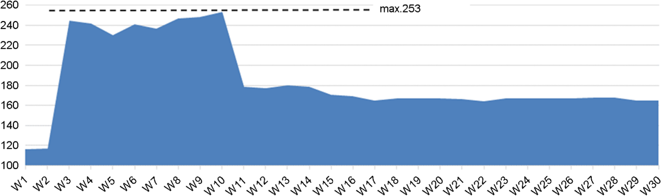
Before normal operation, HUC phase can be divided into 3 steps based on key milestones.
(1) Week 2~9: Offshore facility Hook-up activities start. During this period, no hydrocarbon exists and there is no hydrocarbon related risks.
(2) Week 10~16: Hydrocarbon is ready. Oil production starts but gas systems are inactivated.
(3) Week 17~30: Gas line is connected and gas export starts. Oil and gas both exists on the facility.
As it can be seen, HUC works differ in each stage and related workers get on/off the facility, which result in different manning level in each week.
During HUC, transportation & installation, hook-up, quality management and other workers get on board. As it can be seen in Figure 1, the peak manning level of this facility is Week 10 and after the completion of hook-up, related workers get off and the overall manning level decreases. Therefore, evacuation analysis is performed for the maximum POB 253 in this study.
3.1 Escape, evacuation and rescue system
Escape, evacuation and rescue (EER) system means relevant elements for operators' safe evacuation such as temporary refuge (TR), escape routes, escape means, life-saving appliances and etc. With the increase of POB, evacuation scenarios should be re-established, evacuation time should be re-calculated and integrity of TR if it can accommodate the total POB, additional life-saving appliances and evacuation means should be checked. For this offshore facility, mess room is designated as primary muster area (PMA) where operators can gather in emergency and assessed in terms of increased POB.
3.1.1 Temporary Refuge (TR) area
A muster station shall have sufficient clear deck space to accommodate all persons assigned to muster at that station and it should be at least 0.35m2 per person (MSC, 2020). For an offshore facility, the main TR is designated as PMA and the area of PMA in this offshore facility is 215.6m2. Assuming only 90% of the area is available considering furniture and equipment, the clear space per person is 0.77m2 which meets the requirement.
3.1.2 Life raft
Inflatable life rafts of an approved type are to be provided on board such that their total capacity is sufficient to accommodate the total number of people expected to be on board the facility (ABS, 2014). Therefore, additional life rafts should be temporarily installed for the increased number of POB.
3.1.3 Life jacket
Life jackets should be provided for each person on a facility (ABS, 2014; MSC, 2020). Therefore, 133 life jackets should be additionally installed for the increased number of operators.
3.2 Temporary refuge system
The internal condition of TR system should be reviewed if it can accommodate the increased POB for the required endurance time of EER facilities, which is 60 minutes. In this study, it is assumed that HVAC (Heating, Ventilation and Air Conditioning) system is shut down in PMA and assessed whether the TR can maintain the breathable environment in respect of O2, CO2 concentration levels and the temperature in it.
3.2.1 O2 reduction
The following information is used to calculate the reduction of O2 in the air in the mess room during 60 minutes integrity period with 253 people in the room.
- The volumetric concentration of O2 in dry air is approximately 20.95%
- The tidal volume, which is the lung volume representing the normal volume of air displaced between normal inspiration and expiration when extra effort is not applied, for a healthy, young adult is approximately 500mL per inspiration.
- The average human respiratory rate for adults is 12~20 breaths per minutes. For this assessment 20 breaths per minute is used as a conservative estimate
- The exhaled air contains 4~5% more CO2 and 4~5% less O2 than the inhaled air. In this study, 5% is used as a conservative estimate.
- The minimum permissible O2 concentration in the air to impair the TR is set to be 18% (Table 1)
- Taking into account the presence of people, furniture and other object, the air volume in the TR is 175m2.
- It is assumed that the air remains homogeneous, i.e. the O2 is all the time equally distributed throughout the TR.
Based on the above information, O2 concentration becomes 19.3% after 60 minutes when 253 personnel gather at PMA and this is above the concerned level 18%.
|
% Oxygen in air |
Symptoms |
|
21~20 |
Normal |
|
18 |
Night vision begins to be impaired |
|
17 |
Respiration volume increases, muscular coordination diminishes,
attention and thinking clearly requires more effort |
|
12~15 |
Shortness of breath, headache, dizziness, quickened pulse, effort
fatigues quickly, muscular coordination for skilled movement lost |
|
10~12 |
Nausea and vomiting, exertion impossible,
paralysis of motion |
|
6~8 |
Collapse and unconsciousness occurs |
|
< 6 |
Death in 6 to 8 minutes |
3.2.2 CO2 build-up
In addition to the information listed for O2 consumption, the followings are used to calculate the build-up of CO2 in the air in TR during 60 minutes with 253 people.
- The volumetric concentration of CO2 in the air is approximately 0.039%
- It is assumed that the air remains homogeneous, i.e. the CO2 is all the time equally distributed throughout the TR.
Based on the same method and assumptions, CO₂ build-up due to the respiration of 253 personnel for 60 minutes is 1.71% which is far below the lowest criterion presented in Table 2.
|
CO2 concentration |
Symptoms |
|
45,000 ppm/ 4.5% |
Reduced concentration capability for more than 8 hours exposure,
adaptation possible |
|
55,000 ppm/ 5.5% |
Breathing difficulty, headache and increased heart rate after 1
hour |
|
65,000 ppm/ 6.5% |
Dizziness, and confusion after 15 minutes exposure |
|
70,000 ppm/ 7.0% |
Anxiety caused by breathing difficulty, effects becoming severe
after 6 minutes exposure |
|
100,000 ppm/ 10% |
Approaches threshold of unconsciousness in 30 minutes |
|
120,000 ppm/ 12% |
Threshold of unconsciousness reached in 5 minutes |
|
150,000 ppm/ 15% |
Exposure limit 1 minute |
|
200,000 ppm/ 20% |
Unconsciousness occurs in less than 1 minute |
3.2.3 Temperature rise
The metabolic heat generated in human bodies is dissipated to the environment through the skin and lungs by convection and radiation as sensible heat and by evaporation as latent heat. Also, there are electric equipment and lighting that will emit heat to warm the space and heat transfer will be made from the external environment through the ceiling, wall and floor.
Heat release into the space will be absorbed not only by the air but also by the bulk materials in it e.g. the steel plate with little insulation. In the mess room, the wall and ceiling is insulated but the floor is covered with thin covering and thus considered to absorb the heat. Heat into TR is listed in Table 3 and Table 4.
|
Subject |
Unit |
Value |
|
Sensible heat |
W/person |
67.4 |
|
Latent heat |
W/person |
35.2 |
|
# of persons |
|
253 |
|
Heat from persons |
W |
25,958 |
|
Heat from lighting |
W |
2,606 |
|
Heat from electric equipment |
W |
1,558 |
|
Heat transferred from outside |
W |
2,876 |
|
Safety margin for heat release |
|
5% |
|
Mustering duration |
min |
60 |
|
Total heat released during mustering |
kJ |
124,732 |
|
Temperature requirement |
℃ |
70 |
|
Subject |
Unit |
Value |
|
Volume of air |
m2 |
496 |
|
Margin for net air space |
|
10% |
|
Cv for air at 24℃ |
kJ/kg-K |
0.718 |
|
Floor building weight |
kg/m3 |
54.95 |
|
Weight of surrounding
steel plates |
kg |
13,453 |
|
Heat capacity of air &
floor |
kJ/k |
6,913 |
|
Temperature rise |
℃ |
18 |
As presented in Table 4, the temperature rise of 18℃ is expected after 60 minutes of mustering. Considering the temperature before mustering is 24℃, the final temperature is well below the concerned level of 70℃. As 70℃ is widely applied as HVAC design basis for various offshore projects, 70℃ is applied for the temperature evaluation in this study. Therefore, in terms of O2, CO2 and temperature, PMA can accommodate the increased number of POB.
The primary means of evacuation during HUC phase is gangway, followed by lifeboat and life raft in the order of preference. Even though a helicopter is used for the regular shift of operators to/from shore in normal operation phase, evacuation via helicopter is not practical in most cases given the distance of the facility from the shore and numerous flights are necessary to evacuate the personnel. Instead, an accommodation barge will be positioned next to the offshore facility during HUC stage. Therefore, evacuation to the accommodation barge through gangway is considered most effective and practical and as additional evacuation means, a lifeboat and life rafts are examined.
4.1 Gangway
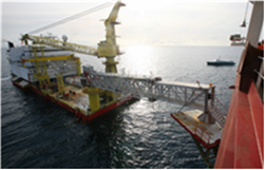
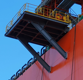
During HUC phase, unlike normal operation stage, gangway attached to the accommodation barge is considered as a preferred means of evacuation. Except for the extreme weather conditions, accommodation barge will normally be connected so it is considered to be the first option to leave the facility when an accident occurs. For the connection of gangway, a temporary platform is installed on the side of the facility as shown in Figure 2 and Figure 3.
4.2 Lifeboat
Each side of embarkation area for lifeboat is equipped with a lifeboat to accommodate the maximum number of personnel on board. Therefore, two lifeboats are stowed on the same floor with PMA and will be used when the gangway is unavailable.
4.3 Life raft
Life rafts are installed one floor down from PMA. When the gangway is unavailable, as the lifeboat cannot accommodate the maximum POB during HUC, life rafts will also be used to leave the installation.
The main purpose of time calculation is to assess the longest time until the completion of evacuation. The remotest areas are identified considering the manning distribution and the access time to a muster area and evacuation time using means of escape are evaluated for different escape routes.
5.1 Methodology
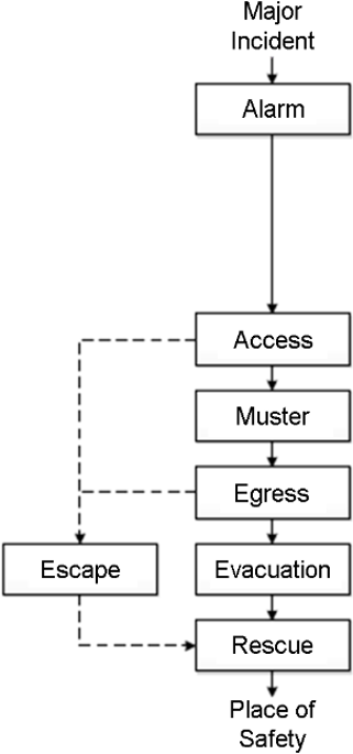
Development of an accidental event varies depending on every situation, but a standard EER sequence can be stipulated as Figure 4. Specific descriptions and possible problems relevant to a project are defined and it is recommended to be tailored for each offshore project. The typical escape and evacuation process consists of the following phases. Actions in each phase of the EER sequence are defined with assumptions based on rules or drill data. Time calculation results by applying assumptions in each stage of Figure 4 and movement speeds in Table 5 are presented below.
The movement speed applied in this study is shown in Table 5.
|
Movement |
Clear condition |
Smoke condition |
||
|
Mean speed (m/s) |
The slowest (m/s) |
Mean speed (m/s) |
The slowest (m/s) |
|
|
Horizontal |
1.30 |
0.88 |
0.40 |
0.27 |
|
Stairs upward |
0.80 |
0.48 |
0.46 |
0.28 |
|
Stairs downward |
0.75 |
0.49 |
0.42 |
0.27 |
|
Vertical ladder |
0.30 |
0.18 |
0.17 |
0.10 |
5.2 Muster (From Alarm)
5.2.1 Alarm
This stage is to detect an incident and sound an alarm. Most dimensioning hydrocarbon accidents can be detected automatically and investigated by central control room. Therefore, it is assumed that detecting an incident and sounding a muster alarm can be made in no later than 2 minutes.
5.2.2 Access
- Respond to alarm: Upon an alarm, evacuees need to do some preparatory works before leaving the work place e.g. making the complicated operation into a safe condition, if needed. All these reactions are assumed to take at most 2 minutes before starting escape.
- Access to a muster area: The time to muster is obtained as the sum of that for moving along horizontal corridors, stairs and/or ladders as shown in Table 5 and that for passing through doors. Doors along the route may introduce another delay which is assumed to be 3 seconds for each swing door, 10 seconds for STP door and 15 seconds for weather & water tight doors and escape hatches at fire water pump room. These additional seconds for passing doors are summed in time calculation.
5.2.3 Muster
At the muster area, the actions of head counts, putting on lifejacket and preparing lifeboats can happen concurrently. A typical duration for 'Roll-call and don lifejacket' is known to be 4 minutes (Spouge, 1999).
From alarm to muster time is calculated based on manning distribution on the facility. Escape routes differ depending on the initial location and the longest time is needed when an evacuee leaves turret, which is a position keeping equipment, which takes 15.95 minutes as shown in Table 6.
|
No. |
Event |
Time (sec) |
Cumulative time (min) |
Action |
|
1 |
Alarm |
120.00 |
2.00 |
Detect an alarm |
|
2 |
Access |
240.00 |
6.00 |
Respond to alarm |
|
321.91 |
11.37 |
Access to PMA |
||
|
35.00 |
11.95 |
Door passing |
||
|
3 |
Muster |
240.00 |
15.95 |
Roll-call and don
lifejacket |
5.3 Egress and evacuation
5.3.1 Egress
The egress time to an embarkation area is obtained as the sum of that for moving along horizontal corridors, stairs and/or ladders and that for passing thorough doors like 'access' stage. The difference is that doors out of a muster area should be passed by all people mustering there, which means it is regarded reasonable to consider the last evacuee should wait for a while until he/she can get out of the area. Total egress time can be expressed as equation (1) and the waiting time for the last evacuee (tdoor-waiting) to the embarkation area can be modelled considering "personnel flow velocity" as equation (2).
where Fs is the specific personnel flow velocity (personnel/meter∙sec), N is the number of people passing the door and B means width of the door (m).
5.3.2 Evacuation
After mustering in TR, whether to evacuate and what evacuation means to use are decided by offshore installation manager and escape routes differ depending on evacuation means. During HUC phase, an accommodation barge is temporarily positioned so evacuation means are considered in the order of gangway, lifeboat and life raft.
- Scenario 1 is the evacuation via gangway. Like Figure 2, a gangway is temporarily connected for workers on board to cross over to another vessel. As the temporary platform is installed on the main deck of the facility, operators should go downstairs from PMA. The time for operators to move to the connection point and to cross the gangway are summed and it is assumed that the maximum allowable number of people on the gangway is restricted to 25. The total time can be tabulated as Table 7.
|
No. |
Event |
Time (sec) |
Cumulative time (min) |
Action |
|
1 |
Egress |
59.17 |
0.99 |
From PMA to the gangway |
|
3.00 |
1.04 |
Door passing |
||
|
244.44 |
5.11 |
Door waiting |
||
|
2 |
Evacuation |
311.09 |
10.30 |
Cross the gangway |
- Scenario 2 includes a lifeboat and life rafts. In case the gangway is unavailable, the evacuation using a lifeboat should be examined. Lifeboats and life rafts for the maximum POB during normal operation are equipped on each side of the facility on different deck levels. However, assuming equipment on the only one side is available, scenario of some using lifeboat and the others using life raft is evaluated. In this case, workers are divided into two groups when leaving the PMA and move to the embarkation area for a lifeboat and life rafts at the same time. In addition to the travel time, launching and boarding time should be considered. When compared, more time is needed for using life rafts than a lifeboat so this is reflected in the time calculation in Table 8.
|
No. |
Event |
Time (sec) |
Cumulative time (min) |
Action |
|
1 |
Egress |
61.50 |
1.03 |
From PMA to the embarkation area |
|
3.00 |
1.08 |
Door passing |
||
|
244.44 |
5.15 |
Door waiting |
||
|
2 |
Evacuation |
600.00 |
15.15 |
Board a life raft |
|
1200.00 |
35.15 |
Launch a life raft |
- Scenario 3 is using only life rafts. As the worst case scenario, evacuation when both gangway and a lifeboat are unavailable is evaluated. This is an extremely rare case especially considering the high availability of the gangway (higher than 90%) and evacuation should be executed by using both existing and additional life rafts. Existing life rafts are davit-launched type so 4 life rafts are installed with davit. For HUC phase, it is practical to install additional throw-overboard type life rafts and store them near PMA. For this type of life raft, operators launch it first on the sea level and board a life raft by moving down the ladder. As simultaneous launching and boarding of two different types of life rafts are possible, the one which takes longer time is included in the total time calculation as Table 9. In case when operators use ladders to board a life raft, it is assumed that maximum 11 persons can climb down the ladder based on the allowable load of the embarkation ladder (ISO, 2008) and weight of a person (MSC, 2017).
|
No. |
Event |
Time (sec) |
Cumulative time (min) |
Action |
|
1 |
Egress |
123.16 |
2.05 |
From PMA to the
embarkation area |
|
3.00 |
2.10 |
Door passing |
||
|
244.44 |
6.18 |
Door waiting |
||
|
2 |
Evacuation |
1250.00 |
27.01 |
Board a life raft |
|
976.00 |
43.28 |
Launch a life raft |
5.4 Total evacuation time
Among various routes, the case which takes the longest time to muster is chosen and then various evacuation scenarios are examined depending on what evacuation means is to be used. Total evacuation time for different evacuation schemes are summarized in Table 10.
|
Scenario |
Alarm to muster |
Egress |
Evacuation |
Total time (min) |
|
1 |
15.95 |
5.11 |
5.18 |
26.24 |
|
2 |
5.15 |
30.00 |
35.15 |
|
|
3 |
6.18 |
37.10 |
59.23 |
As offshore production facilities are not only operated for a long time but also far from shore, the safety of operators is a key factor for successful operation and evacuation is one of the important aspects of the safety. There are a number of different requirements on the overall time to complete evacuation for commercial vessels, drilling rigs, passenger ships, etc. For this facility, the allowable time for EERA is be the time during which TR can maintain its functionality, which is 60 minutes. This study has meaning in that quantitative evaluation was performed on the evacuation safety regarding the actual offshore production facility. This study shows how evacuation plans can be made and what should be considered. In this study, three (3) evacuation scenarios are established and they all satisfy the time requirement.
Due to the lack of information on shift workers, the total number of workers during HUC phase was reflected in this study. However, if night shift workers are excluded, the total evacuation time can be reduced and the time can be calculated more precisely.
As the total number of people is the most essential factor in evacuation, hook-up and commissioning phase when the number of operators increase substantially should be examined apart from normal operation phase. Through this evaluation, evacuation schemes can be established and appropriate guidance can be given to operators on board in advance.
References
1. American Bureau of Shipping (ABS), Rules for Building and Classing – Facilities on offshore installations, American Bureau of Shipping, Houston, 2014.
2. Building Research Establishment (BRE) Ltd, OTH 533 Emergency Way Guidance Lighting Systems – Phase 1, Health and Safety Executive, United Kingdom, 1998.
3. International Association of Oil and Gas Producers (IOGP), Report No. 434-14 Risk Assessment Data Directory – Vulnerability of humans, International Association of Oil & Gas Producers, United Kingdom, 2010.
4. International Association of Oil and Gas Producers (IOGP), Report No. 434-19 Risk Assessment Data Directory – Evacuation, escape & rescue, International Association of Oil & Gas Producers, United Kingdom, 2010.
5. International Organization for Standardization (ISO), ISO 13702 Petroleum and natural gas industries – Control and mitigation of fires and explosions on offshore production installations, ISO Copyright Office, Geneva, 2015.
6. International Organization for Standardization (ISO), ISO 5489 Ships and marine technology – Embarkation ladders, ISO Copyright Office, Geneva, 2008.
7. Spouge, J., Guide to Quantitative Risk Assessment for Offshore Installations, Center for Marine and Petroleum Technology (CMPT), United Kingdom, 1999.
8. The Maritime Safety Committee (MSC), International Convention for the Safety of Life At Sea (SOLAS), International Maritime Organization (IMO), London, 2020.
Google Scholar
9. The Maritime Safety Committee (MSC), International Life-Saving Appliances (LSA) Code, International Maritime Organization (IMO), London, 2017.
10. Watanabe, Y., Nayuki, K. and Torizaki, K., Actions of firemen in smoke, Report of Fire Research Institute of Japan, 37(9), 15-19, 1973.
PIDS App ServiceClick here!